
Application #23. Design of Tiltrotor Configuration
Taken from the following publication, available in the Publications area of the website:
Nielsen, E.J., Diskin, B., and Yamaleev, N.K., “Discrete Adjoint-Based Design Optimization of Unsteady Turbulent Flows on Dynamic Unstructured Grids”, AIAA 2009-3802, June 2009.
(Requires Flash player to view)
This example is a three-bladed tiltrotor configuration similar to that used by the V-22 aircraft and is based on the Tilt Rotor Aeroacoustics Model (TRAM) geometry. The grid used for this computation is designed for a blade collective setting of 14 degrees and consists of 5,048,727 nodes and 29,802,252 tetrahedral elements. The rotational speed of the rotor is held constant at a value corresponding to a tip Mach number of 0.62 in a hover condition. The Reynolds number is 2.1 million based on the blade tip chord. The physical time step is chosen to correspond to 1 degree of rotor azimuth, for a total of 360 time steps per revolution. The BDF2opt formulation is used with 10 subiterations per time step.
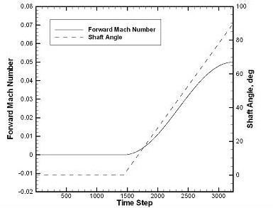
Figure 1. Forward Mach number and shaft angle schedule for TRAM rotor simulation.
For this test, the prescribed rigid mesh motion consists of 4 initial revolutions of the geometry designed to reach a quasi-steady hover condition, followed by five additional revolutions during which a 90 degree constant-rate pitch-up maneuver into a forward-flight mode is performed. A more realistic pitch-up scenario might consist of many more revolutions; however, the prescribed motion was chosen to keep the cost of the computation affordable on the current resources. During the pitch-up phase of the motion, an assumed forward-flight velocity profile based on a simple sine function is imposed through the mesh speed terms. The schedule for the shaft angle and forward-flight velocity is shown in Fig. 1, where the shaft angle is defined to be 0 degrees in the hover condition and 90 degrees in forward flight. The resulting motion is shown in Fig. 2. An isosurface of the second invariant of the velocity-gradient tensor, also known as the Q criterion, at the time step corresponding to 1440 degrees is shown in Fig. 3. The tip vortex system is maintained for 2 to 3 revolutions of the rotor.
Figure 2. View of TRAM rotor motion.
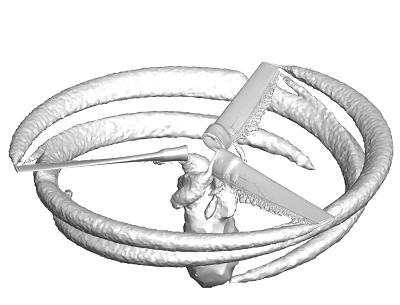
Figure 3. Isosurface of Q criterion for TRAM rotor at 1440 degrees.
The objective function for the current test case is to maximize the rotor thrust coefficient over the time interval corresponding to the pitch-up maneuver. The baseline thrust profile is shown as the solid line in Fig. 4. After the first four rotor revolutions, the thrust coefficient has reached a quasi-steady value of approximately 0.015, which is in good agreement with experimental data. The thrust coefficient shows a discontinuous behavior at the impulsive start of the pitch-up motion and gradually decreases to a lower constant value in the forward-flight condition. A subtle 3/rev oscillation in the thrust coefficient during the pitch-up maneuver can also be seen.
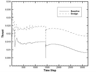
Figure 4. Thrust for TRAM rotor before and after design optimization.
The surface grid has been parameterized as shown in Fig. 5. This approach yields a set of 44 active design variables describing the thickness and camber of the blade geometry; thinning of the blade is not allowed. In addition, a single twist variable is used to modify the blade collective setting during the design.
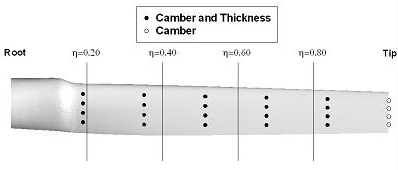
Figure 5. Spanwise blade and design variable locations for TRAM rotor.
The convergence history for six design cycles is shown in Fig. 6. The optimizer quickly reduces the value of the objective function over the first two design cycles, after which further improvements are minimal. Closer inspection of the design variables indicates that the majority of values have reached their bound constraints, preventing any further reduction in the objective function. The final thrust coefficient profile is included as the dashed line in Fig. 4. Cross-sections of the baseline blade geometry are compared with the optimized geometry in Fig. 7. The optimization has increased the camber of the blade across the span, as well as the blade collective setting.
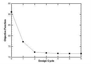
Figure 6. Objective function history for TRAM rotor.
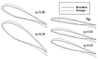
Figure 7. Spanwise blade cross-sections before and after optimization of TRAM rotor.
This example has been performed using 128 dual-socket quad-core nodes with 3.0 GHz Intel Xeon processors in a fully-dense fashion for a total of 1,024 computational cores. The cost of each solution to the unsteady flow and adjoint equations for the current example is approximately 3.5 and 10.5 wallclock hours, respectively; however, due to frequent file I/O, this estimate varies with file system load. The optimization procedure requires twelve calls to the flow solver and six calls to the adjoint solver, for a total runtime of approximately 4.5 days of wallclock time or 110,000 CPU hours. The disk storage required for one complete flow solution is approximately 1.5 terabytes.
NASA Official: David P. Lockard
Contact: FUN3D-support@lists.nasa.gov
Page Last Modified: 2026-07-22 15:23:24 -0400
NASA Privacy Statement
Accessibility
This material is declared a work of the U.S. Government and is not subject to copyright protection in the United States.