
Application #24. Design of F-15 with Simulated Aeroelastic Effects
Taken from the following publication, available in the Publications area of the website:
Nielsen, E.J., Diskin, B., and Yamaleev, N.K., “Discrete Adjoint-Based Design Optimization of Unsteady Turbulent Flows on Dynamic Unstructured Grids”, AIAA 2009-3802, June 2009.
(Requires Flash player to view)
This example uses a deforming grid approach to simulate aeroelastic motion of a modified F-15 fighter jet configuration known as NASA research aircraft #837, shown in Fig. 1. The computational model assumes half-plane symmetry in the spanwise direction. The grid consists of 4,715,852 nodes and 27,344,343 tetrahedral elements and includes detailed features of the external airframe as well as the internal ducting upstream of the engine fan face and plenum/nozzle combination downstream of the turbine. For the current test, the freestream Mach number is 0.90, the angle of attack is 0 degrees, and the Reynolds number based on the MAC is 1 million. The static pressure ratio at the engine fan face is set to 0.9 and the total pressure ratio at the plenum face is ramped linearly from 1.0 to its final value of 5.0 over the first 50 time steps.
Figure 1. Modified F-15 with engine duct geometry.
The prescribed grid motion consists of 5 Hz 0.3 degree oscillatory rotations of the canard, wing, and tail surfaces about their root chordlines, with the wing oscillations 180 degrees out of phase with the canard and tail motion. In addition, the main wing is also subjected to a 5 Hz oscillatory twisting motion whose amplitude decays linearly from 0.5 degrees at the wing tip to 0 degrees at the wing root and takes place about the quarter-chord line. This composite motion is shown in Figs. 2-5. The BDF2opt scheme is used with 10 subiterations and a physical time step corresponding to 100 steps per cycle of grid motion.
Figure 2. Simulated aeroelastic motion of F-15 geometry.
Figure 3. Simulated aeroelastic motion of canard geometry.
Figure 4. Simulated aeroelastic motion of wing geometry.
Figure 5. Simulated aeroelastic motion of tail geometry.
The unsteady lift-to-drag ratio (L/D) for the baseline configuration undergoing the specified motion for 300 time steps is shown as the solid line in Fig. 6. The L/D behavior begins to exhibit a periodic response after approximately 100 time steps. The high-frequency oscillations in the profile are believed to be due to a small unsteadiness in the engine plume shown in Fig. 7; this behavior is also present when the mesh is held fixed.
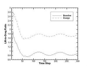
Figure 6. Unsteady L/D profile before and after optimization.
Figure 7. Cross-section of unsteady engine plume effects.
The objective function for the current test case is to maximize L/D on the timestep interval 201-300. The surface grids for the canard, wing, and tail have been parameterized as shown in Fig. 8, resulting in a set of 98 active design variables describing the thickness and camber of each surface. Thinning of the geometry is not permitted.
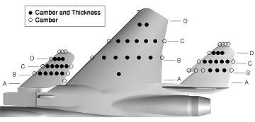
Figure 8. Spanwise and design variable locations for modified F-15.
Convergence of the objective function is shown in Fig. 9. A large reduction in the function is obtained after a single design cycle, after which further improvements are minimal due to many of the design variables having reached their bound constraints. The final L/D profile is included as the dashed line in Fig. 6. The resulting shape changes at various spanwise stations on the canard, wing, and tail are shown in Fig. 10, where the vertical scale has been exaggerated for clarity. The design procedure has increased the thickness of the wing and canard, as well as the camber across all three elements. Closer inspection shows that the trailing edges of each surface have also been deflected in a downward fashion.
This example has been performed using 128 dual-socket quad-core nodes with 3.0 GHz Intel Xeon processors in a fully-dense fashion for a total of 1,024 computational cores. The wallclock times required for single flow and adjoint solutions for the current problem are approximately 1 and 1.5 hours, respectively. For the five design cycles shown in Fig. 9, the optimizer requires ten flow solutions and five adjoint solutions, or a total wallclock time of approximately 18 hours or 18,400 CPU hours. The disk space necessary to store a single unsteady flow solution is 136 gigabytes.
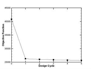
Figure 9. Objective function history.
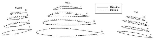
Figure 10. Canard, wing, and tail cross-sections before and after optimization of modified F-15.
NASA Official: David P. Lockard
Contact: FUN3D-support@lists.nasa.gov
Page Last Modified: 2026-07-22 15:23:25 -0400
NASA Privacy Statement
Accessibility
This material is declared a work of the U.S. Government and is not subject to copyright protection in the United States.