Application #56. Various 2D Adjoint-Based Airfoil Designs
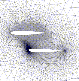
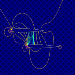
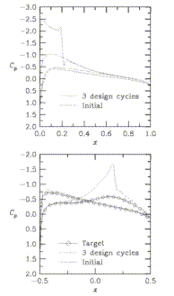
This set of results is from some past work on the continuous adjoint method on unstructured grids. This test case is for a 2-element airfoil where the objective is to modify the pressure distribution on the front airfoil by changing the shape of the aft airfoil. Results are shown after 3 design cycles.
This image shows the grid used for the design case.
This image shows the pressures contours.
This image shows a comparison of target, initial, and final pressure distributions.
Laminar Airfoil
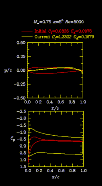
This result is for a compressible, viscous case. The freestream Mach number is 0.75, the Reynolds number is 5000, and the angle of attack is fixed at 5 degrees. The objective in this case is simply to increase the lift coefficient with no attention paid to the drag or the feasibility of the design. As seen in the pressure distributions shown in the figure, the lift has been increased by about a factor of 16. It is evident that the final airfoil is not very practical because it is extremely thin.
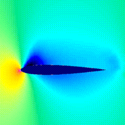
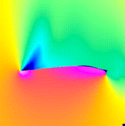
Contours of the pressure coefficient are shown below for the initial and the final geometries.
Turbulent Airfoil
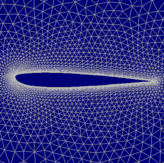
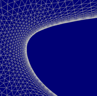
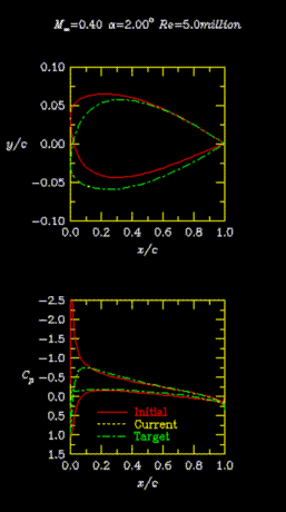
The next 2 results are for compressible, turbulent flows over airfoils. For these calculations, the turbulence model (Spalart-Allmaras) has been differentiated and included in the solution of the costate variables along with the density, momentum, and energy. For both cases shown, the spacing at the wall is 1E-5 and the turbulence model is integrated all the way to the wall. The first case is for an airfoil that I just made up. The Mach number is 0.4, the angle of attack is 2 degrees, and the Reynolds number is 5 million based on the chord of the airfoil. The grid is shown in the figures below. There are only 3 design variables for this case.
The goal of the optimization was simply to match a desired pressure distribution. There are only 3 design variables for this case so the process converges fairly quickly. As can be seen, the desired pressure distribution is obtained very well and is indistinguishable from the original. Similarly, the airfoil shape returns to that of the original shape that was used for getting the target pressures.
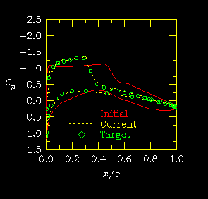
This next case is more difficult because there are 75 design variables. The Mach number is 0.725, the angle-of-attack is 2.54 degrees, and the Reynolds number is 6.5 million. The grid used for this is very similar to that for the previous case and so it is not shown. This case is not quite converged but the pressures match the desired ones reasonably well.
Turbulent Airfoil with Curvature Constraints
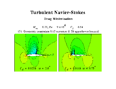
The last case is another viscous design case. This time, the objective is to reduce the drag. In addition, there are 152 constraints placed on the geometry. Many of the constraints deal with the curvature so the nose radius is not too small and the curvature is positive over the upper surface. In addition, there are 38 constraints which define upper and lower bounds for the design variables. The conditions are a freestream Mach number of 0.75, a Reynolds number of 9 million, and a lift coefficient of 0.53.
NASA Official: David P. Lockard
Contact: FUN3D-support@lists.nasa.gov
Page Last Modified: 2026-01-16 12:03:13 -0500
NASA Privacy Statement
Accessibility
This material is declared a work of the U.S. Government and is not subject to copyright protection in the United States.


